How to Measure Reflected Power Using the TPI-1006 RF Signal Generator
In this video, I demonstrate how to measure reflected power using the TPI-1006 RF Signal Generator and a 20 dB directional coupler. This process helps measure how much power is reflected back from a device under test—typically used to determine return loss or match quality.
Key Takeaways
- The TPI-1006 provides accurate reflected measurements using a simple directional coupler.
- It can match results from a much more expensive network analyzer.
- This tool is compact, versatile, and ideal for RF testing in the lab or field.
- Engineering classrooms can afford this powerful tool for training.
- Ham operators can measure antenna VSWR and cable losses.
Watch the Demo
Want to see it in action? Watch the full video here to follow along with the setup and see the TPI-1006 deliver professional-grade performance.
Step-by-Step Walkthrough: How to Measure Reflected Power Using the TPI-1006 RF Signal Generator
1. Set Up the Analyzer
I start by switching the measurement mode to “Reflected.” When prompted, I confirm that I’m sure I want to make this change.
Next, I:
- Set the center frequency to 2440 MHz (bandpass filter center frequency)
- Set the span to 25 MHz for close in measurement. Can be set to 500MHz as well to see the rolloff of the filter.
These settings give a focused view of the reflected signal across a narrow frequency range.
2. Configure the Directional Coupler
I use a 20 dB directional coupler, which I’ve found to work well for this setup. Here’s how I connect it:
- The RF output of the TPI-1006 connects to the output port of the coupler.
- The coupled port of the coupler connects to the TPI-1006 detector input.
- The input port of the coupler is left unconnected.
This setup routes forward power to the device under test and captures reflected power for measurement.
3. Start the Measurement
With the analyzer still set to “Reflected,” I begin the measurement. The software detects the loss in the coupler system. I let it run once, then store the result.
The return loss at this point is set to 0 dB, which is expected without a load connected.
4. Connect the Bandpass Filter
I now connect a 2.4 GHz bandpass filter, terminated with a 50-ohm load. This simulates a realistic device under test.
After connecting it, I select “reflected” and rerun the measurement. The result now shows a return loss of approximately -17 dB at 2.44 GHz, which indicates a good impedance match with minimal reflection.
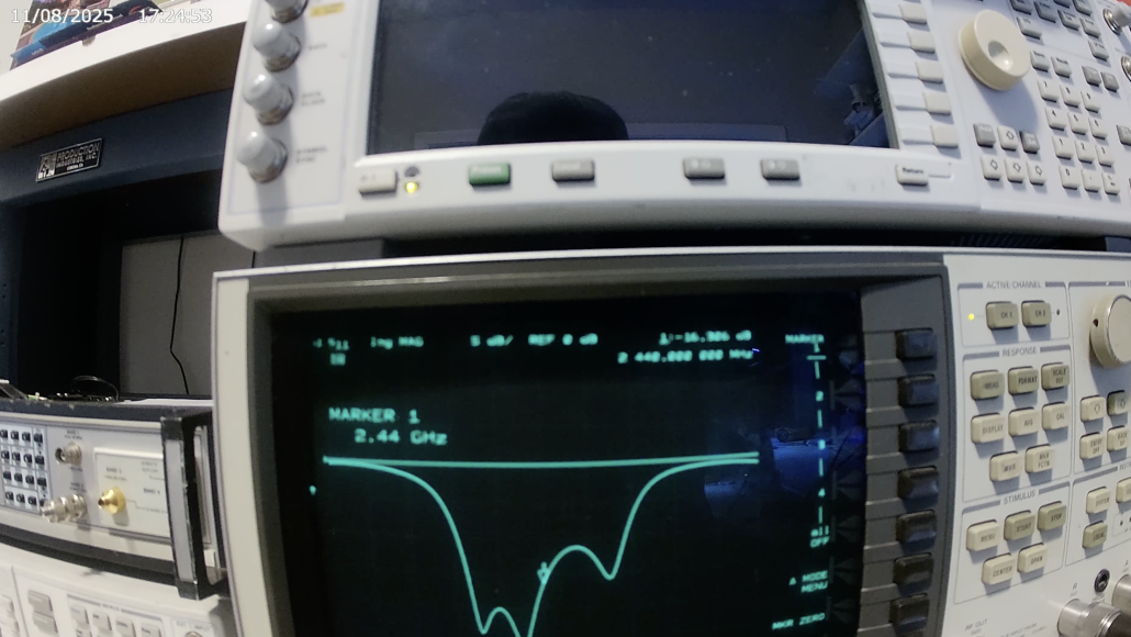
5. Verify with a Network Analyzer
To validate the measurement, I connect the same setup to a traditional HP Network Analyzer.
The network analyzer reports a return loss of -16 dB, almost identical to what the TPI-1006 reported. This consistency shows how accurate and powerful the TPI-1006’s built-in scalar analyzer is.


