Screenshot of forward response measurement using the TPI-1006 RF signal generator from RF Consultant

In this demonstration, I walk through the process of how to measure a forward response using the TPI-1006 RF Signal Generator and a bandpass filter. This kind of test is helpful for analyzing the filter’s insertion loss and verifying its frequency characteristics.

Key Takeaways

  • The TPI-1006 RF Signal Generator allows precise forward measurements with minimal setup.
  • This test confirms the insertion loss and band shape of a standard 2.4 GHz filter.
  • Increasing the resolution helps clarify the behavior of the filter’s transition regions.

Watch the Demo

Want to see the process in real time? Watch the full video here to follow along as I measure and analyze a bandpass filter using the TPI-1006.

Step-by-Step Walkthrough: How to Measure Forward Response with the TPI-1006 RF Consultant Signal Generator

1. Zero Out the Cable

As with any network analyzer test, the first step is to zero out the cable to establish a proper baseline. This ensures the measurement reflects only the performance of the device under test—not the cable.

2. Configure the Analyzer

  • The analyzer is set to Forward Mode
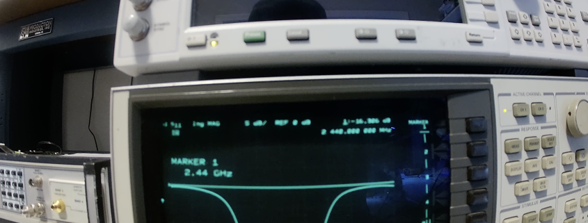
  • Center frequency: 2.44 GHz
  • Span: 300 MHz
  • Y-axis scale: Starts at 0 dB, lowered down to -65 dB

These settings give us a full view of the filter’s forward response across the band of interest.

3. Capture Baseline Measurement

After the initial sweep is complete, I hit Store to lock in the baseline (with no filter connected).

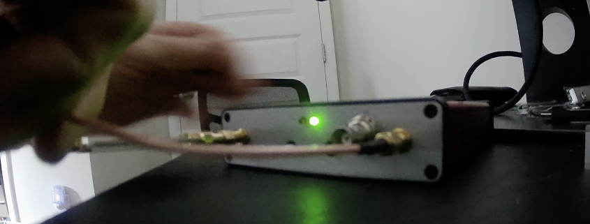
4. Insert the Bandpass Filter

Next, I connect the 2.4 GHz bandpass filter and run the test again to measure its insertion loss.

To get a clearer view of the filter skirts, I increase the Span to 600 Mhz, giving better resolution and detail on the filter shape.

5. Review the Results

The results show an insertion loss of about 1 dB, which is expected for this filter. The response curve confirms the filter is working correctly, with sharp cutoffs and minimal signal loss in the passband.

Measuring reflected power with the TPI-1006 RF signal generator from RF Consultant

In this video, I demonstrate how to measure reflected power using the TPI-1006 RF Signal Generator and a 20 dB directional coupler. This process helps measure how much power is reflected back from a device under test—typically used to determine return loss or match quality.

Key Takeaways

  • The TPI-1006 provides accurate reflected measurements using a simple directional coupler.
  • It can match results from a much more expensive network analyzer.
  • This tool is compact, versatile, and ideal for RF testing in the lab or field.
  • Engineering classrooms can afford this powerful tool for training.
  • Ham operators can measure antenna VSWR and cable losses.

Watch the Demo

Want to see it in action? Watch the full video here to follow along with the setup and see the TPI-1006 deliver professional-grade performance.

Step-by-Step Walkthrough: How to Measure Reflected Power Using the TPI-1006 RF Signal Generator

1. Set Up the Analyzer

I start by switching the measurement mode to “Reflected.” When prompted, I confirm that I’m sure I want to make this change.

Next, I:

  • Set the center frequency to 2440 MHz (bandpass filter center frequency)
  • Set the span to 25 MHz for close in measurement. Can be set to 500MHz as well to see the rolloff of the filter.

These settings give a focused view of the reflected signal across a narrow frequency range.

2. Configure the Directional Coupler

I use a 20 dB directional coupler, which I’ve found to work well for this setup. Here’s how I connect it:

  • The RF output of the TPI-1006 connects to the output port of the coupler.
  • The coupled port of the coupler connects to the TPI-1006 detector input.
  • The input port of the coupler is left unconnected.

This setup routes forward power to the device under test and captures reflected power for measurement.

3. Start the Measurement

With the analyzer still set to “Reflected,” I begin the measurement. The software detects the loss in the coupler system. I let it run once, then store the result.

The return loss at this point is set to 0 dB, which is expected without a load connected.

4. Connect the Bandpass Filter

I now connect a 2.4 GHz bandpass filter, terminated with a 50-ohm load. This simulates a realistic device under test.

After connecting it, I select “reflected” and rerun the measurement. The result now shows a return loss of approximately -17 dB at 2.44 GHz, which indicates a good impedance match with minimal reflection.

5. Verify with a Network Analyzer

To validate the measurement, I connect the same setup to a traditional HP Network Analyzer.

The network analyzer reports a return loss of -16 dB, almost identical to what the TPI-1006 reported. This consistency shows how accurate and powerful the TPI-1006’s built-in scalar analyzer is.