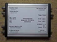
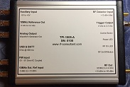
The following table compares the features of the TPI Signal Generators:
| TPI-1001
| TPI-1002
| TPI-1005
| |
|---|---|---|---|
| Frequency: 35 MHz to 4.4 GHz | ✓ | ✓ | ✓ |
| Maximum output level | +10 dBm | +10 dBm | +12 dBm |
| Minimum output level | −90 dBm | −70 dBm | −90 dBm |
| Stand-alone operation or PC controlled | ✓ | ✓ | ✓ |
| Internal or external 10 MHz reference | ✓ | ✓ | ✓ |
| Reference output | ✓ | ✓ | ✓ |
| Automatic output level control | ✓ | ✓ | |
| Square wave modulation (internal square wave) | ✓ | ✓ | ✓ |
| Square wave modulation (external square wave) | ✓ | ✓ | |
| Frequency scan during square wave modulation | ✓ | ✓ | ✓ |
| Beacon mode | ✓ | ✓ | ✓ |
| Modulation script | ✓ | ✓ | ✓ |
| Frequency modulation (external signal) | ✓ | ✓ | ✓ |
| Frequency modulation (internal sine/triangle wave) | ✓ | ||
| Frequency modulation (internal DTMF generator) | ✓ | ||
| Waveform generator output (sine, triangle, square) 4 | ✓ | ||
| DTMF generator output 4 | ✓ | ||
| FM controls loop filter or VCTCXO | ✓ | ||
| Frequency and/or level scan | ✓ | ✓ | ✓ |
| RF power meter (external input) | ✓ | ✓ | |
| Scalar network analyzer | ✓ | ✓ | |
| Control script | ✓ | ✓ | ✓ |
| Auxiliary input (trigger input) | ✓ | ✓ | |
| Trigger output | ✓ | ✓ | |
| Programmable control button | ✓ | ✓ | ✓ |
| Measure return loss & VSWR 1 | ✓ | ✓ | |
| DC voltmeter (+5 V to −5 V) 2 | ✓ | ✓ | |
| Output sweep marker at settable frequency 3 | ✓ | ✓ | |
| Square wave and pulse generator 3 | ✓ | ✓ | |
| Detector comparison to level threshold 3 | ✓ | ✓ | |
| External voltage controlled output level 2 | ✓ | ✓ | |
| External voltage controlled output frequency 2 | ✓ | ✓ |
1 Requires external directional coupler
2 Uses auxiliary input
3 Uses trigger output
4 Uses waveform output
2 Uses auxiliary input
3 Uses trigger output
4 Uses waveform output


